Inverter LED Signals Guide
SMA Inverter LED Signals
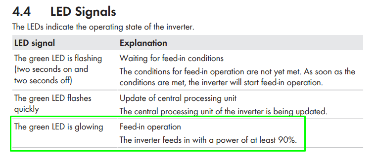
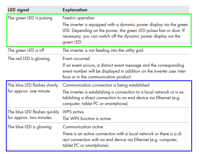
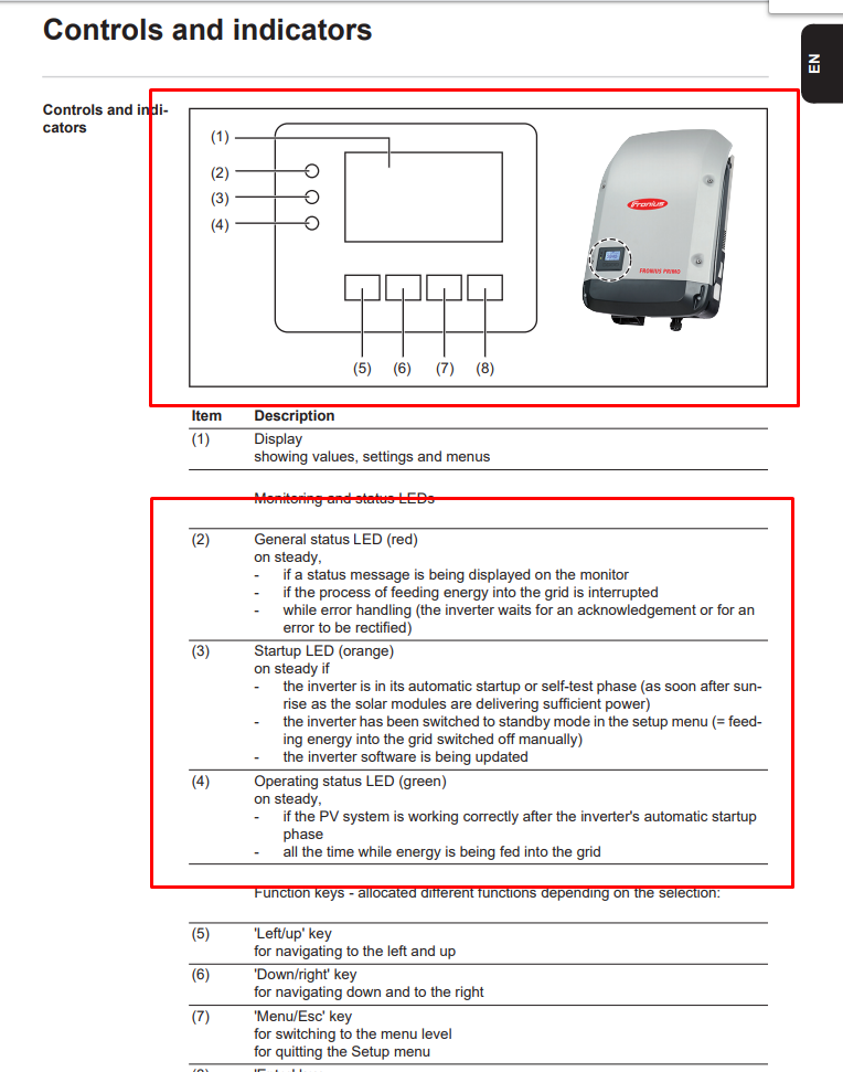
Fronius Inverter LED Signals
SolarEdge Inverter LED Signals
Power One PVI Indoor Models LED Signals

1 – Power, Green in colour.
2 – Fault, Red in colour
3 – EFI, Orange in colour
Normal Operation Mode
As long as no LED or only the green LED is on, the Inverter is in its normal operating status. If the green LED is flashing, the inverter is in its initializing phase which is a normal operating state as well. All other signals indicate a disturbed operating state. Refer to the inverter manual for more information on the different LED signal codes.
Power One PVI 2000 Outdoor Models


1 – Power, Green in colour.
2 – Fault, Red in colour
3 – EFI, Orange in colour
4 – Button
Normal Operation Mode
As long as no LED or only the green LED is on, the Inverter is in its normal operating status. If the green LED is flashing, the inverter is in its initializing phase which is a normal operating state as well. All other signals indicate a disturbed operating state. Refer to the inverter manual for more information on the different LED signal codes.
PVI Aurora LED Quick Reference Guide:
| LED Status | Operational Status | Remarks |
|
1: Off 2: Off 3: Off |
Aurora self-disconnection during night time | Input voltage less than 90 Vdc at both inputs. |
|
1: Flashing 2: Off 3: Off |
Aurora initialization, settings loading and waiting for grid check | It is a transition status while operating conditions are checked. |
|
1: On 2: Off 3: Off |
Aurora is powering the grid | Standard machine operation (search of max. power point or constant voltage). |
|
1: Any condition 2: Any condition 3: On |
System insulation device fault | Ground leakage found. |
|
1: Off 2: On 3: Off |
Defect – fault | The Fault can be inside or outside the machine. See the alarm appearing on the LCD. |
|
1: Off 2: Flashing 3: Off |
Installation phase: Aurora is disconnected from grid | During installation, it refers to set-up of the address for RS-485 communication. |
|
1: Off 2: On 3: Off |
Grid disconnection | Indicates a missing grid condition. |
SMA Inverters Operating Mode Indication:
The SMA inverter displays the actual operating status with three LEDs on the inverter lid.
Sunny Boy Range

Sunny Mini Central Range

Sunny Boy TL Range

Sunny Boy HF Range
Normal Operation Mode
As long as no LED or only the green LED is blinking, the Sunny Boy is in its normal operating status. If all three LEDs are on, the inverter is in its initializing phase which is a normal operating state as well. All other signals indicate a disturbed operating state. Refer to the inverter manual for more information on the different LED signal codes.
SMA Inverter LED Quick Reference Guide:
| LEDs Status | Operational Status | Remarks |
|
1: Off 2: Off 3: Off |
Standby at night | This indicates that the DC voltage at the inverter is too low to be fed into the grid. |
|
1: On 2: On 3: On |
Initialisation | The inverter is in the initialisation phase. Operating conditions are being checked. |
|
1: On 2: Off 3: Off |
Feeding Operation | Successfully completed the self-test, synchronised to the grid andexporting power. |
|
1: Flashing 2: Off 3: Off |
Stop Mode / Waiting –Monitoring Mode | Calibration of the measurement electronics is being carried out. Verifying the required conditions for operation are fulfilled. If all are fulfilled then grid monitoring will be started. |
|
1: Flashing (1 per sec) 2: On or Flashing 3: Off |
Earth Fault / Insulation Failure | Indicates an earth fault of one of the two thermally monitored varistors on the DC input side is defective. In this condition feeding to the utility grid is suspended, until the failure is rectified. |
|
1: Off 2: Off 3: On |
Inverter permanently disabled | Failure of the grid monitoring or the independent disconnection device (MSD) within the unit. During the internal testing process, the inverter has detected a malfunction of the MSD and has stopped feeding to the grid. This is a failure which cannot be rectified on site. |
|
1: Any Condition 2: Any Condition 3: Flashing |
Grid problem | Indicates a grid failure which can be caused by: Grid under-voltage, Grid over-voltage, Grid under frequency, Grid over-frequency. First find out whether there is a general power shutdown. |
|
Below only applies to HF and TL range. |
||
|
1: Any Condition 2: Any Condition 3: Flashing or On |
Bluetooth | Flashing indicates that the inverter has been identified by Sunny Explorer. On indicates that it has been incorporated into a Bluetooth Networ |
Before contacting the service centre, keep the following information close at hand, to maximise efficiency of intervention:
NOTE: Information to be found directly on the LCD display
- Inverter model & make?
- Serial number?
- Week of production?
- LED flashing?
- Light blinking or steady?
- Which signal is shown on the display?
- Short description of the malfunction
- Can the malfunction be reproduced? If so, how?
- Does the malfunction appear cyclically? If so, how frequently?
- Is malfunction present from installation? If so, has it worsened?
- Description of the weather conditions at the time the malfunction appeared
- INFO on the Photovoltaic Field
- Make and model of photovoltaic panels
- System structure: – number of arrays and max. voltage and current values
– number of strings for each array
– number of panels for each string